- Qualcomm Launches Snapdragon 4 Gen 2 Mobile Platform
- AMD Launches Ryzen PRO 7000 Series Mobile & Desktop Platform
- Intel Launches Sleek Single-Slot Arc Pro A60 Workstation Graphics Card
- NVIDIA Announces Latest Ada Lovelace Additions: GeForce RTX 4060 Ti & RTX 4060
- Maxon Redshift With AMD Radeon GPU Rendering Support Now Available
ASUS Commando
ASUS has been on a roll with their RoG line of motherboards. Their third installment, Commando, looks to impress enthusiasts with the help of Intels P965 chipset. How does this board stack up against others, and is it worthy of the Republic of Gamers name?
Page 3 – Board Layout
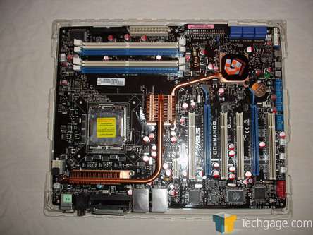
Looking at the board as a whole, the layout is solid and clean. The board itself is dominated by a copper heatpipe running through the center. This not only looks good, but also helps to transport heart away from both the southbridge and northbridge as well as the voltage regulators. As stated earlier, when an air cooler is used, air will be pushed across the top heatsink to help keep everything cool. When water cooling is used, the included fan is needed to keep your system temps in check.
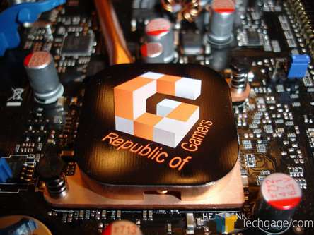
Covering the southbridge is a small, almost passive heatsink with the RoG logo on the top. This is where the heatpipe starts its journey upwards.
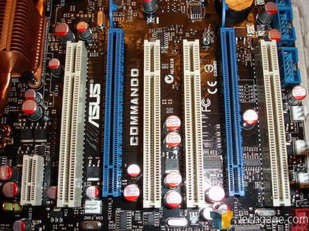
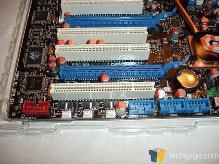
Directly to the side of the southbridge, places exactly where they should be, is the PCI-E and PCI 2.2 slots. Notice the PCI-E x1 looking slot at the top (left in this picture.) This is not to be used with anything other than the SupremeFX audio card included with the Commando. Just under it is one PCI slot.
The next expansion slot is the first x16 PCI-E slot, followed by 2 more PCI slots, the final PCI-E slot and finally, the last PCI 2.2 slot. Take note though, the PCI-E slots are not your average x8 by x8 slots when using 2 GPUs. The top one is x16 and the bottom one is unfortunately x4. This is not the fault of Asus, but rather of the chipset as a whole… unless you want to blame Asus for using the P965 altogether. We will hold off judgment until we start testing.
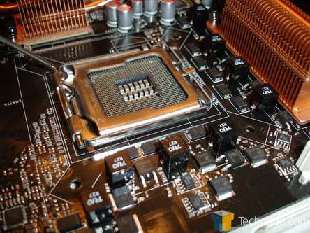
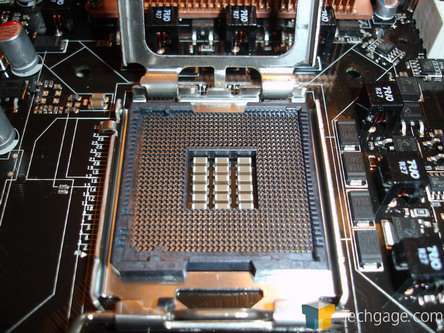
Moving onto the CPU area, we can see the 8 phase voltage system used by Asus.
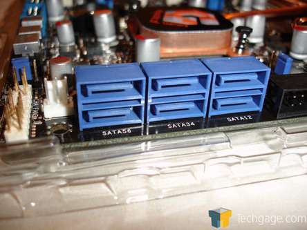
Working out way down the side of the motherboard, we come to the six 90 degree SATA 3.0 Gb/s ports. I personally like these at the 90 degree angle as it helps the overall appearance of the motherboard when installing in a case.
Just to the right of the SATA ports is the floppy connector.
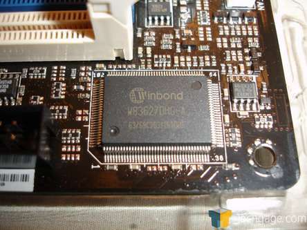
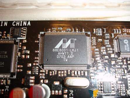
Looking at some of the various chips around the Commando, we come across a Winbond chip and a Marvell Ethernet chip used to power one of the 2 onboard NICs.
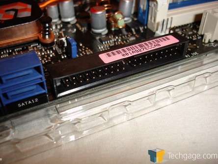
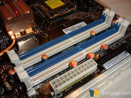
Moving to the DDR2 DIMM slots, we see them color coded for those running dual channel RAM. I would venture to guess that this is about 95% of all users and is nice to see. These will run DDR2 533, 667 and 800 MHz memory. Just beside the DIMM slots, we see the power 24 pin power connector as well as the IDE connector.
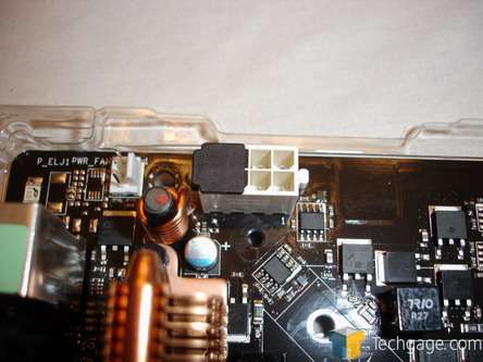
Not happy with just one power connection, the Commando, and all other 775 motherboards for that matter, needs another 8-pin power connection. This can be found just above CPU and to its left in the top left hand corner of the motherboard. There is a cap on four of the pins. Should you only have a 4-pin connector, this can be used to keep dust and whatever you have floating around in your air out of the open four pins.
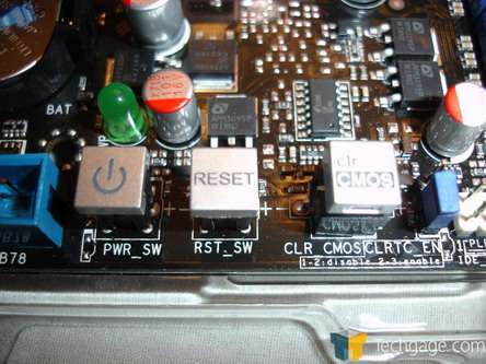
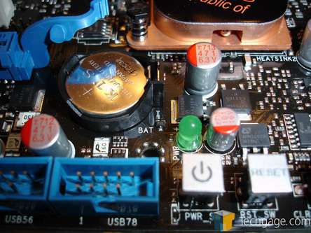
At the bottom right of the motherboard, we see a set of buttons. These are have become more and more popular with the enthusiasts as it allows them to have full functionality with the motherboard outside of a case on, say, a bench. Asus as taken this one step further and again catering to the enthusiast crowd, and placed a clear CMOS button on the board as well. Gone are the days or small little jumpers, or better yet, removing the CMOS battery to clear a bad overclock. Simply press this button down when the PC is off and you are off to the races again.
Just above the buttons, we find the CMOS battery and the power LED. Also, to the left of the power button, there is the USB pins for an external USB port such as the PCI one included in the bundle.
Rounding out the bottom of the motherboard, we have, in order from right to left, the FireWire headers, 3 fan controllers and the three USB headers.
Getting to the back of the Commando, the I/O ports is where the RoG motherboards start to pull away from the pack. Most notably, there is a LCD display that will give POST status and report error codes should the system hang during boot. When running normally, this will display the time. While this is a nice addition, how many people, benchers aside, will have clear access to the back of their motherboard?
|
|
Support our efforts! With ad revenue at an all-time low for written websites, we're relying more than ever on reader support to help us continue putting so much effort into this type of content. You can support us by becoming a Patron, or by using our Amazon shopping affiliate links listed through our articles. Thanks for your support!


