- Qualcomm Launches Snapdragon 4 Gen 2 Mobile Platform
- AMD Launches Ryzen PRO 7000 Series Mobile & Desktop Platform
- Intel Launches Sleek Single-Slot Arc Pro A60 Workstation Graphics Card
- NVIDIA Announces Latest Ada Lovelace Additions: GeForce RTX 4060 Ti & RTX 4060
- Maxon Redshift With AMD Radeon GPU Rendering Support Now Available
A Look at Upcoming ASUS H67 & P67 Motherboards
Intel’s Sandy Bridge processors are rumored to be delivered within the next two months, and some proof of that is the fact that motherboard vendors are coming forth with lots of information about their upcoming product. ASUS is one of these, and has briefed us on a large collection of its H67 & P67 offerings. Let’s check ’em out.
Page 1 – Introduction; Maximus IV Extreme & P8P67 EVO/Pro
It isn’t much of a secret that Intel’s next-generation Sandy Bridge processor series is right around the corner. Although they will share the same 32nm fabrication process as current Lynnfield family processors, the similarities mostly end there. Most notable of which is that Sandy Bridge processors will require a new LGA1155 socket, and as such will be paired with the upcoming P67 and H67 chipsets.
The primary difference is P67 will not include the required video ports needed to take advantage of the integrated graphics built into Sandy Bridge processors, while the H67 series motherboards will include these ports by default.
Of course a new socket also means a fresh series of motherboard designs, and ASUS has given us the green light to release at least a little information on its upcoming motherboards! To be clear we are not allowed to discuss several of the more interesting features that ASUS will be implementing, but otherwise we can cover the main boards of interest and show off some teaser photos.
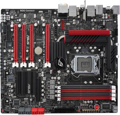
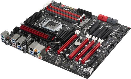
First on the list we have the Republic of Gamers flagship, the P67 Maximus IV Extreme. By now the RoG series should need no introduction as it targets enthusiasts, overclockers, and as the name implies, extreme overclockers. What could possibly make this board extreme? Well for starters it offers a special LN2 mode that can be enabled via a toggle switch next to the big red Start button.
Additionally there is a thermal sensor built into the socket dedicated to directly measuring the temperature of the CPU pad contacts. Given socket pins have been shown to melt easily under extreme conditions this should prove reassuring for heavy overclockers and useful for sub-zero overclockers alike.
Of course, this alone wouldn’t make the Maximus IV Extreme worthy of the ASUS Republic of Gamers name. As seen on previous motherboards such as the Rampage III Extreme there are voltmeter probe contacts that (combined with included probe sleeves) will allow easy checking of board-level voltages. Specifically the DRAM, CPU_SA, NF200, PCH_PLL, PCH, CPU_I/O, CPU_PLL, and CPU voltages are the nine voltmeter points available below the Start and Reset buttons.
For users that prefer the utmost in manual control of their motherboards, next to these are the physical switches that toggle between the various PCIe slot configurations, although these can also simply be configured via the BIOS.
We did mention the LN2 mode, right? As such a single EPS12V connector to power the processor directly might be a tad underwhelming, which is why there is an additional molex connector located in the “sweet spot” behind the sound ports to supply additional power. There is a second 4-pin molex connector located at the bottom edge of the motherboard below the PCIe slots, likely there to provide additional power to overclocked graphics cards.
On the connectivity front (perhaps in a desperate bid to offset all the red elsewhere on the motherboard) we have a whopping total of eight blue USB 3.0 ports on the back I/O panel. A single multi-purpose PS/2 port, optical SPDIF, 8-channel sound, dual eSATA, dual Intel gigabit LAN, Bluetooth, and a single USB 2.0 port round off the back I/O panel options.
As for switches there is the obligatory BIOS clear, Bluetooth, and RoG connect buttons, with power, reset, and clear BIOS switches also directly on the motherboard itself. Two more USB 3 ports will be available with the additional 3.5″ bay adapter ASUS will include on some model boards, enabling a grand total of no less than ten USB 3 ports for this single motherboard. At that point we understandably forgot to inquire as to how many USB 2.0 ports would be available through port headers on the motherboard.
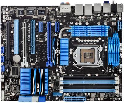
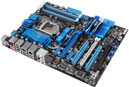
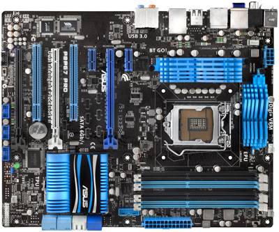
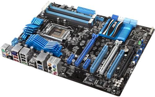
Up next we have the more mainstream board, the P8P67 EVO Deluxe. For the back I/O panel there are two PS/2 ports, optical & coaxial SPDIF ports, three eSATA ports, Bluetooth, FireWire, four USB 2.0, two USB 3.0, one powered eSATA port, dual gigabit LAN ports, BIOS reset switch, and last but not least the 8-channel audio jacks. The rest of the features are to be expected, namely power/reset switches directly on the PCB, four SATA 6Gb/s ports, and additional connectivity for two more front USB 3.0 ports.
Interestingly, the only notable missing feature would be the lack of any diagnostic code LEDs on this board. ASUS smartly designed a 3.5″ bay box that will provide two front USB 3.0 ports and solve the issue of no front USB 3 for the majority of PC cases that currently exist. ASUS will be selling a lower cost non-Deluxe “Pro” version of the P8P67 EVO that forgoes this feature.
Speaking of which, here’s the P8P67 EVO Pro model. Not a whole lot changes, although board-level power and reset buttons have been removed, and supposedly the 3.5″ bay extender for front USB 3.0 ports is not included. Again there are no diagnostic LEDs, but the Deluxe was missing these to begin with so that is to be expected. The only other noticeable difference would be a slight reduction in power circuitry around the PCIe slots. For those wondering, both the dark blue and the white SATA ports are 6Gb/s, the only difference is one is connected to the Intel southbridge while the other is handled by a third party controller.
One last feature to briefly mention is that the P8P67 EVO motherboards offer physical (and presumably also BIOS) switches to enable/disable EPU and TPU. ASUS terms these “Dual Intelligent Processors II”, and each performs rather different yet related functions. The TPU will provide monitoring functions for the motherboard’s digital VRM power circuitry, while the EPU actually regulates the power appropriately based on need or configured settings. This may sound slightly basic, but some of the power regulation options provided by the ASUS Suite II rely on this capability to function.
Support our efforts! With ad revenue at an all-time low for written websites, we're relying more than ever on reader support to help us continue putting so much effort into this type of content. You can support us by becoming a Patron, or by using our Amazon shopping affiliate links listed through our articles. Thanks for your support!


