- Qualcomm Launches Snapdragon 4 Gen 2 Mobile Platform
- AMD Launches Ryzen PRO 7000 Series Mobile & Desktop Platform
- Intel Launches Sleek Single-Slot Arc Pro A60 Workstation Graphics Card
- NVIDIA Announces Latest Ada Lovelace Additions: GeForce RTX 4060 Ti & RTX 4060
- Maxon Redshift With AMD Radeon GPU Rendering Support Now Available
Social & RSS Feeds
Latest Videos

Latest News
ASUS P9X79-E WS Workstation Motherboard Review
by Rob Williams on October 23, 2013 in Motherboards
If a workstation build is in the cards, or you’re looking to build the baddest multi-GPU gaming rig around, the X79 platform remains the one to consider. But what motherboard could possibly fill the “ultimate” void, one that’s able to handle a lot of stress, or for that matter, 7 graphics cards? Look no further than ASUS’ P9X79-E WS.
Page 2 – A Hardware Tour of ASUS P9X79-E WS
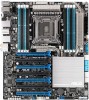
To kick-off our P9X79-E WS hardware tour, we’ll take a look at the ASUS-provided overview image, which we verified to be exact to the sample we received.
If the point wasn’t driven home well enough on the last page, the biggest feature to set the P9X79-E WS apart from most other X79 boards out there is that 7x PCIe slots are provided for those who need to build the biggest GPU setups around, either for gaming or something like Folding@home.
These 7 slots are colored blue and black for a reason: Dual-slot GPUs will plug into the blue slots, allowing 4 cards to be installed and ruling out the black slots from being used. In a similar manner, when it comes to using just four sticks of RAM, the blue slots should be used rather than the black. Because the socket/DIMM area of the motherboard is rather tight, it’s recommended that RAM without tall heatspreaders be used, unless the CPU heatsink won’t reach the DIMM slots, or liquid-cooling is used.

Being the workstation board that it is, the P9X79-E WS anticipates a rather ridiculous power load. Thus, a 6-pin power connector located above the PCIe slots can be used to help drive additional power to the lanes being used – it does not drive power anywhere else.

Before moving on, it’s worth pointing out that the board includes a total if six 4-pin fan connectors: 1x on each side of the board, and 2x beneath the CPU socket. I have no complaints about where these are located, and am in fact rather pleased.
At the top-right corner of the board, we can see a 4-pin fan connector both to the right, and up top. On either side of the 24-pin power connector are the toggles to enable/disable Dr. Power (we’ll talk about this in the conclusion) or EPU, and beside the latter, onboard Power / Reset buttons.

A better – but not as sexy – angle showing the above can be viewed here.
The next image serves no other purpose but to give you an idea of how the board will be managed once installed into a chassis. Given hassles with 8-pin power connectors I’ve experienced in the past, I prefer to see these connectors located at the absolute top and on a horizontal plane, but given the amount of stuff going on in this area, I have to assume that ASUS was forced into this implementation.

The above image served a minor purpose, but this next image has it beat: It’s just meant to look cool. And it does. As mentioned before, no reasonable CPU cooler should be difficult to install here, though I’d recommend avoiding memory with tall heatsinks to avoid potential problems. If liquid-cooling is involved, memory form-factor won’t matter.

The bottom-right of the board has a lot going on, so from the absolute bottom corner and moving to the left, we have: Chassis connectors, USB 2.0 internal header (which happens to be an actual USB port), a TPM header, dual USB 2.0 headers, another 4-pin fan header, and a COM port header to the left of that.

A better look:

Worth noting is the LED BIOS readout situated above the chassis connectors. The inclusion of this is always a major plus in my book – despite its simplicity, it can really help get to the bottom of PC boot issues fast.
This, is something to behold:

Underneath the PCIe slots (which we’ve discussed enough already) is the TPU toggle, and to the right, a CLRTC dip-switch that can be moved so that when the PC reset button is hit, the PC will boot straight into the EFI.
The I/O panel at the back is replete with connectivity options: 10x USB 2.0, 2x USB 3.0, 2x eSATA 6Gbps, BIOS Flashback button, S/PDIF output, 6x audio connectors, a PS/2 port and the dual Intel NIC ports (a great feature on a board like this).

Accessories included with the P9X79-E WS include a manual, driver DVD-ROM, 2-way SLI bridge, 3-way SLI bridge, 4-way SLI bridge, I/O panel cover…

… 8x SATA 6Gbps cables, 2x SATA 3Gbps cables, molex-to-SATA power adapter…

… COM port bracket (when is the last time you saw one of those?) and Firewire + USB 2.0 bracket. All of this makes for a heavier-than-expected box.

It’s clear that the P9X79-E WS packs a lot, and the only thing really “missing” might be Thunderbolt (which would have been nice to see here, but it adds a hell of a premium), and wireless – a feature that most workstation users are not going to miss.
Is the EFI as robust as the hardware? Given what we’ve seen from ASUS before, we can assume that to be the case, so let’s make sure it proves true this time around.

Support our efforts! With ad revenue at an all-time low for written websites, we're relying more than ever on reader support to help us continue putting so much effort into this type of content. You can support us by becoming a Patron, or by using our Amazon shopping affiliate links listed through our articles. Thanks for your support!

Rob Williams
Rob founded Techgage in 2005 to be an 'Advocate of the consumer', focusing on fair reviews and keeping people apprised of news in the tech world. Catering to both enthusiasts and businesses alike; from desktop gaming to professional workstations, and all the supporting software.


