- Qualcomm Launches Snapdragon 4 Gen 2 Mobile Platform
- AMD Launches Ryzen PRO 7000 Series Mobile & Desktop Platform
- Intel Launches Sleek Single-Slot Arc Pro A60 Workstation Graphics Card
- NVIDIA Announces Latest Ada Lovelace Additions: GeForce RTX 4060 Ti & RTX 4060
- Maxon Redshift With AMD Radeon GPU Rendering Support Now Available
DFI LanParty UT NF590 SLI-M2R/G
DFIs highly anticipated AM2 enthusiast board is finally here, after months of development. Like previous LanParty boards, this one caters to the overclocker, and simply checking out the BIOS screams that fact. Does it please this enthusiast? Read on…
Page 2 – Board Layout
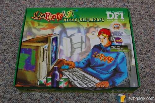
It’s not difficult to predict what LanParty boxes will look like… each new one is usually just a different color. No exception here!
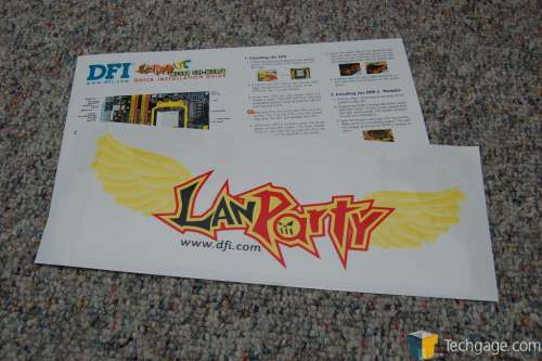
Though catered as an enthusiasts board, DFI has included a colorful manual explaining how to install the board, CPU and memory. Also included is a huge clear decal for your case. Good for showing your support to DFI at lan parties.
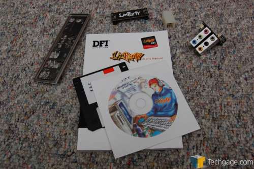
There are not that many extras included with the board, but what you will require is supplied. There is a motherboard back plate, SLI bridge, audio card, manual, diskette for RAID drivers and the motherboard installation CD-Rom.
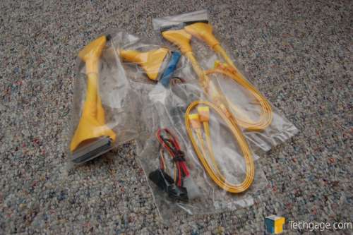
In terms of connectors, we have 4 S-ATA, one IDE with two ends, a floppy connector and a S-ATA power converter for use with a 4-Pin Molex connector.
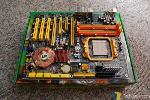
Here it is, in all it’s orange/yellow glory. At first look, the board looks quite similar to the old Ultra-D, but there are a few immediate differences. The first thing that caught my eye was the placement of the ram slots… I was not sure about this at first but they haven’t caused me issues yet. Actually, cooling the ram has proved easier with this placement. Prior, I just shoved a 120mm fan in with all of the loose PSU cords and hoped it stayed put. Now, since it’s directly in line with the PSU, I taped the fan onto the bottom of it to blow air straight at the modules. Ghetto, yes, but efficient.
One complaint with the Ultra-D was the fact that the north bridge chipset heatsink was directly at the end of the PCI-E slot, and here is no difference. I can’t say I am terribly impressed by this, but I can’t see a reason it would be problematic either, unless for some reason the chipset was severely overheated. The CPU bracket is another part that I found odd. The notches are at the top and bottom rather than the left and right, so this will reflect how you will need to install your cooling. I found this was better in my case though, because the waterblock was easier to install and ended up leaving more room in that area. So, it didn’t affect me, but it may for others.
You might already be asking yourself, “Where in the heck are the S-ATA ports? I only see two.” In the top picture, they are right below the chipset cooler… instead of being exposed like the other two, these are on the side of the board. The reason for this is clear… if you have a RAID setup, you will have a lot of cables sticking up, but this way they come out to the side and are easier to keep tidy.
Overall I can’t complain too much about the layout. Only thing I would have loved to see are more available fan power connectors closer to the chipset. There is only one in that vicinity, and it’s right below the bottom PCI slot. I had to use a 3-Pin to 4-Pin fan converter in order to use the power cords directly from my PSU because I could not reach any of the available fan ports on the motherboard from where it was situated.
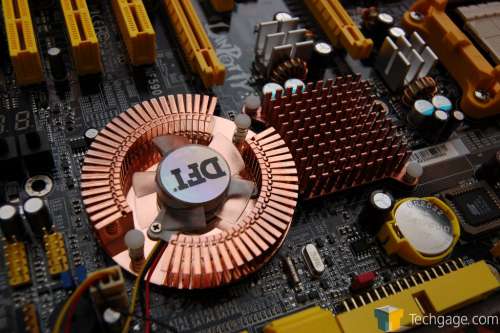
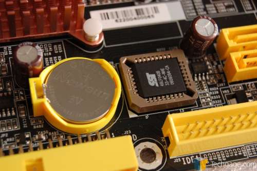
Here is a closeup of the north bridge and south bridge, in all of it’s coppery goodness! Also pictured is the BIOS battery and it’s reset switch (red). The actual BIOS chip is found directly beside the battery.
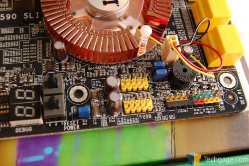
As you would expect, there is a slew of available connections at the bottom of the board, including the color coded ATX case connectors. One thing I am pleased to see are the two USB connections right here… and not further down the board. This makes it far easier to reach and maintain a clean bottom of the case. As we’ve come to expect with recent motherboards, there is also a Power/Reset button here for those who are working outside of a case. There are two numbered LED’s that show debug codes, so if you are running into issues, the proper code will be displayed here for you to investigate.
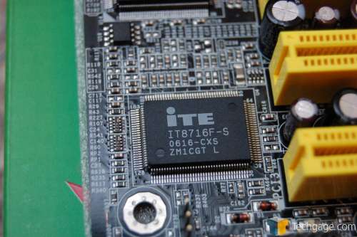
Here is the ITE IT8716F-S monitoring chip that is found on many nForce AM2 motherboards.
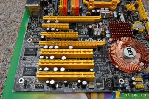
An overview of the 2x PCI-E slots, 1x PCI-E 1x, 1x PCI-E 4x and 2 PCIs. There is also a com port connector and also a single fan connector.
|
|
Support our efforts! With ad revenue at an all-time low for written websites, we're relying more than ever on reader support to help us continue putting so much effort into this type of content. You can support us by becoming a Patron, or by using our Amazon shopping affiliate links listed through our articles. Thanks for your support!


