- Qualcomm Launches Snapdragon 4 Gen 2 Mobile Platform
- AMD Launches Ryzen PRO 7000 Series Mobile & Desktop Platform
- Intel Launches Sleek Single-Slot Arc Pro A60 Workstation Graphics Card
- NVIDIA Announces Latest Ada Lovelace Additions: GeForce RTX 4060 Ti & RTX 4060
- Maxon Redshift With AMD Radeon GPU Rendering Support Now Available
NZXT Duet
Home Theater PCs are the fastest-growing trend in home computing. Here’s an in-depth look at enthusiast case maker NZXT’s first HTPC case, the Duet. With its tasteful looks, clever design, and ample cooling, this case has serious potential.
Page 4 – Building a System
For this part, I contacted my local friend and fellow PC enthusiast Colin, who had some extra hardware and a free afternoon to spend helping me out. The goal: have a working HTPC by the end of the day. To accomplish this, we’ll be moving his current system from its old home, an Antec SLK3700, into the Duet. This will be no easy task – his system uses no fewer than three hard drives. Before attempting to move the hardware, we recorded idle and load temperatures inside the SLK3700 for use in later comparison.
- Test System
- AMD Athlon 64 X2 3800+ CPU
- Cooler Master Vortex TX CPU Cooler
- ASUS A8N-VM-CSM Micro ATX Motherboard
- eVGA NVIDIA 7600GT KO 256MB
- ATI TV Wonder 650 Tuner
- Creative Sound Blaster Audigy4
- 3 Hard Drives (One Seagate, Two Maxtor)
- One DVD-RW Drive
- Antec TruePower 350 Power Supply, 350W
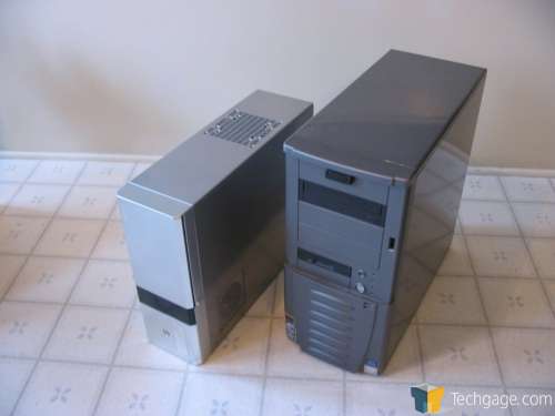
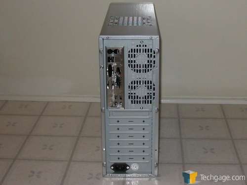
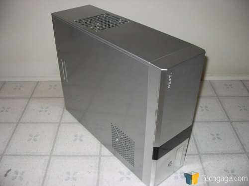
Placing the Duet case beside the SLK3700 case reveals that both have about the same length, though the Duet is shorter and narrower. Smaller cases tend to run hotter, since the components are confined in a smaller surrounding thermal mass. The process of building a system in this case will be quite different from what most enthusiasts are used to, so I’ve gone to great lengths to document it thoroughly.
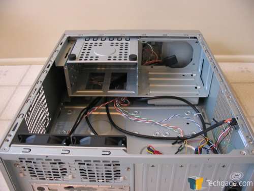
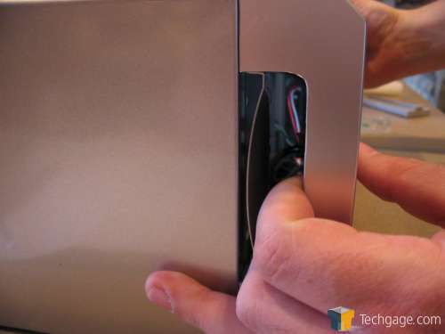
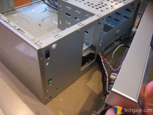
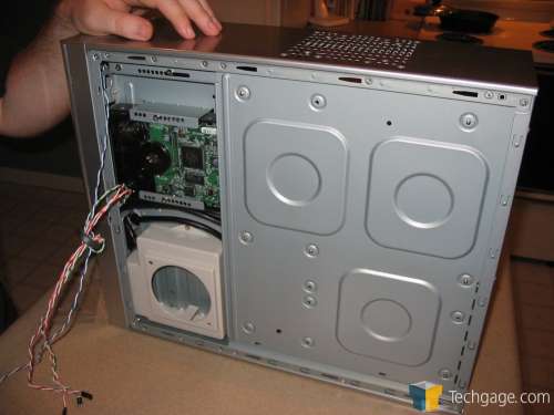
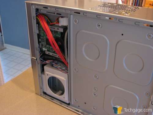
The first task in building a system in the Duet is installation of the power supply. The power supply mounts in the front of this case, exhausting toward the bezel. A duct covers the exhaust fan of the power supply and causes it to turn 90 degrees. The air makes a second turn inside the plastic fan duct; removing this duct causes the warm air from the power supply to be dumped inside the case instead of channeled outward through the side vent. Later, I’ll show you a scenario where removing the fan duct may make sense. To begin mounting the power supply requires the removal of the front bezel; thankfully, this task is easy. Simply grab the handle at the left end of the front bezel (nearest the PSU) and pull firmly outward.
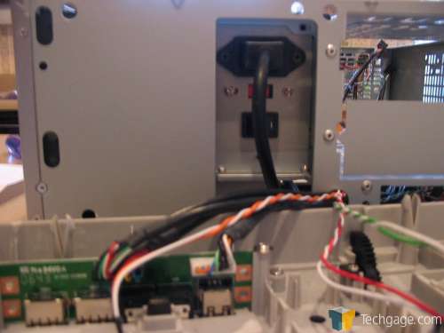
Once the front panel has been removed, place the power supply into the tray, aligning the IEC male connector and power switch in the window as shown. Connect the short AC cable to the PSU. Then, screw the power supply to the case chassis. Personally, I think that a right-angle plug would have been appropriate here instead of the straight plug used by NZXT, to make connection of the power cable as easy as possible.
In addition, screwing the power supply to the chassis requires putting screws through some very small holes. I recommend the use of a magnetic screwdriver for this operation, to prevent losing the screws down inside the bowels of the case. Also, for the sake of your sanity, make sure the power switch on the power supply is turned on before replacing the front bezel. Don’t replace the bezel just yet – the 5.25″ drives must be loaded from the front of the case on the provided plastic rails.
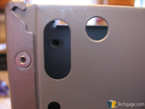
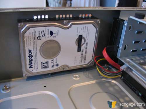
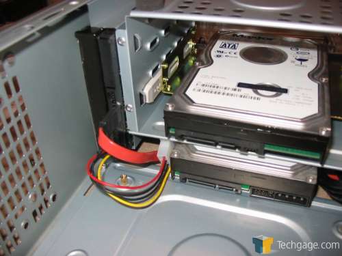
The next task is to mount the three 3.5″ hard drives. There is one physical internal 3.5″ bay, though NZXT provides mounting holes on the end vents for mounting hard drives directly over them. Colin and I agreed that this was silly – mounting a hard drive over the vent covers it almost completely. Instead, we mounted one hard drive in the internal 3.5″ bay, another in the external 3.5″ bay (where the floppy drive would typically be placed), and the third drive in one of the 5.25″ bays using converter rails. In this way, we were able to mount all three hard drives without sacrificing airflow through the system. It would have been nice if NZXT had added some perforations for drawing air across the hard drives, especially the one mounted in the single internal bay.
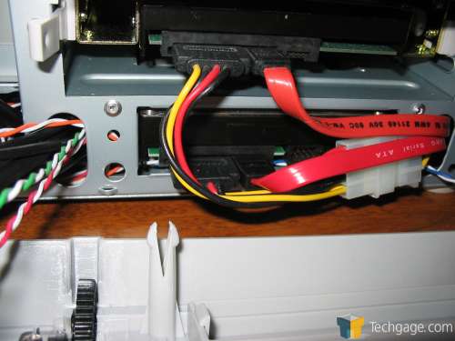
The SATA power and data connectors to the hard drive mounted in the external 3.5″ bay interfered physically with the motherboard, so we reversed its mounting as well as the mounting of the drive in the 5.25″ bay, since the two drives shared a two-headed SATA power connector. There was just enough clearance inside the front bezel to allow this method of cable routing.
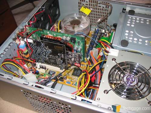
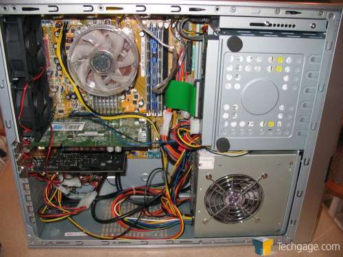
Once the hard drives were in place, we swapped out the I/O panels and inserted the motherboard, with CPU and memory already installed. Then it was time to install the expansion cards. The first expansion slot uses a removable slot cover held in place with a screw. However, the rest of the expansion slot covers were of the tear-off type. These covers were slammed by Rob Williams in the review of the NZXT Adamas as well; in a case that generally retails for nearly $80, we should not have to deal with these tear-off slot covers that can’t be replaced. Unfortunately, this will have to be a strike against NZXT.
I can only recommend that builders exercise care when determining which of these covers they will tear off, since once they’re gone, there’s no replacing them except with covers and screws cannibalized from other cases. The Duet will accommodate full-height expansion cards, though cards that are taller than full-height (like XFX GeForce7-based video cards with the passive heatpiped heatsink and other cards with certain aftermarket coolers) won’t fit.
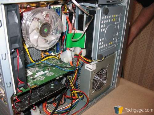
Once the motherboard and expansion cards were mounted, we connected the power connectors and reinstalled the factory-supplied case fans. The NZXT case provides several options for connecting the front panel audio, USB, and Firewire ports. The connectors for the front panel audio connectors provide clustered connectors for Intel HD Audio and AC ’97 audio output, as well as individual pins for motherboard audio connectors with non-standard pinouts.
The front panel Firewire and USB connectors received the same treatment. One gripe: the cable for the front-panel power LED had only a two-pin connector, which wouldn’t work with our ASUS motherboard’s 3-pin power LED output. We tried different ways of installing the connector, but none of them worked. You’d think that after all this time, case manufacturers would include an adapter of some sort, or that motherboard manufacturers would adopt a standard, but this isn’t the first case I’ve encountered that has had this problem.
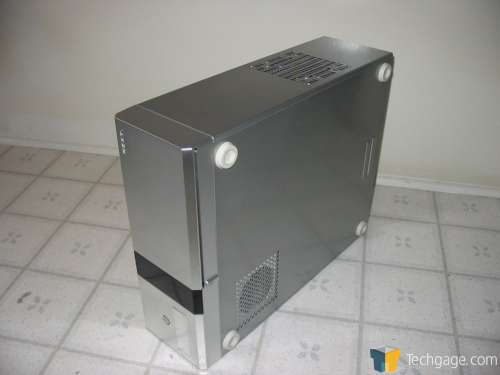
Finally, we were able to close up the case and apply the feet. The case will be used horizontally, so the feet were applied to the bottom of the case. Note that the duct where the power supply exhausts its air will be on the bottom of the case. If you use this case horizontally, you’ll need to be sure that there is some clearance beneath the case to allow the unrestricted exhausting of air. The supplied feet provide sufficient clearance, but don’t place this case horizontally on carpeting.
|
|
Support our efforts! With ad revenue at an all-time low for written websites, we're relying more than ever on reader support to help us continue putting so much effort into this type of content. You can support us by becoming a Patron, or by using our Amazon shopping affiliate links listed through our articles. Thanks for your support!


