- Qualcomm Launches Snapdragon 4 Gen 2 Mobile Platform
- AMD Launches Ryzen PRO 7000 Series Mobile & Desktop Platform
- Intel Launches Sleek Single-Slot Arc Pro A60 Workstation Graphics Card
- NVIDIA Announces Latest Ada Lovelace Additions: GeForce RTX 4060 Ti & RTX 4060
- Maxon Redshift With AMD Radeon GPU Rendering Support Now Available
DFI Infinity 975X/G
Long known for their overclocker friendly motherboards, DFI is back with a board for the highly popular and extremely powerful Core 2 Duo. Using Intels 975X chipset, the DFI Infinity 975 X/G looks to introduce the enthusiast crowd to Conroe, DFI style. Using the BIOS that shipped with the board, we got less than spectacular results, forcing us to go with a popular Beta. How high could we get the FSB and is the board worth it?
Page 2 – Packaging & Layout
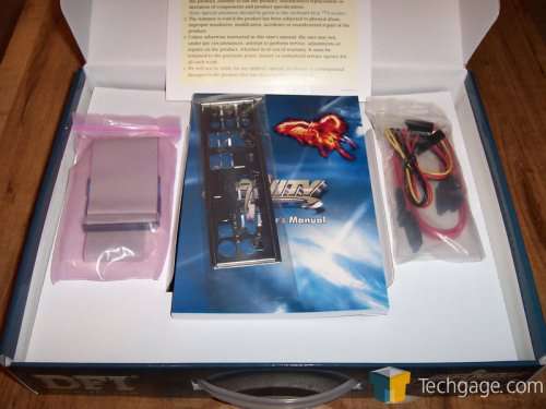
Once open, we see that DFI has included a few essential cables and that’s it. DFI is clearly holding true to the Infinity “budget” labeling. This is not a big deal for most, knowing that an Infinity purchase isn’t going to net you an insane amount of extras. The Infinity is almost a polar opposite of the LanParty in this regard. This is actually nice to be honest. The no nonsense approach allows DFI to keep costs down a bit as well as give the end user all that they will need to get going, but that’s about it.
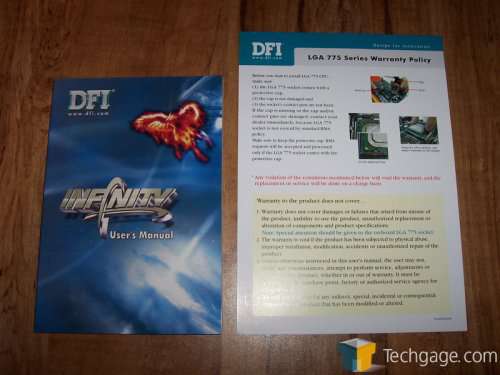
Here we see the manual. For most, this is the first item that is thrown to the side. I personally keep mine around for various information in case I need it.
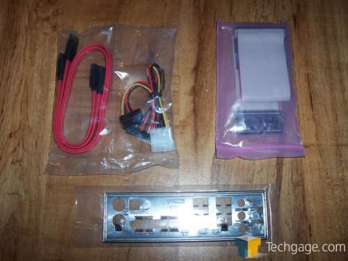
Next we see the I/O plate, one IDE ribbon, a pair of SATA cables as well as one 4-pin molex to SATA power connector. As stated before, not a lot, but just enough to get your PC build off the ground.
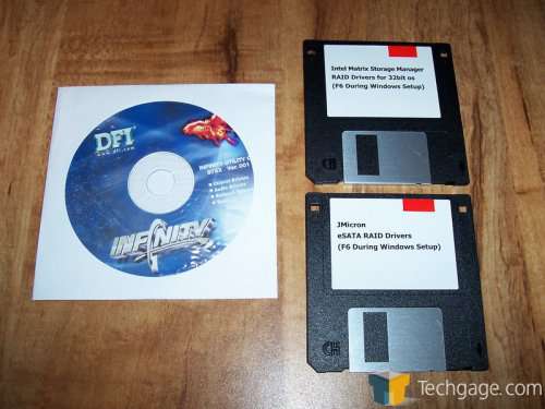
Finally we get to the driver disks. With the need for RAID drivers in XP, DFI has included a pair of 3.5” driver disks as well as a CD with all of the necessary Windows drivers on it. These drivers include the chipset drivers, ATI and NVIDIA video display drivers, Ethernet drivers and many more. Also included on the disk is Smart Guardian PC monitoring software.
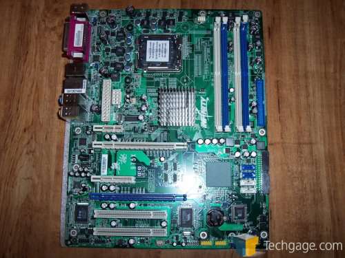
Moving past the packaging and included bundle, we move to the Infinity 975 X/G itself. With a rather bland looking green PCB, the 975 X/G certainly lacks the bling that other motherboard posses but is this really a problem?
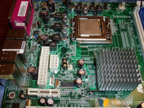
The first thing that we notice is the passive northbridge. Held down by a retention wire, the aluminum heatsink passively cools the northbridge with fairly tall fins. With 96 fins in all, there is certainly a lot of surface area to keep the northbridge cool and does so completely silent.
If we move from there, just to the left of the northbridge, we see the power connectors. This, to me, is an odd place to put these connectors as the PSU cables will have to run either on top of the CPU cooler or just above or below. This also could effect the northbridge cooling as there won’t be an active fan cooling the chip and the PSU cables running so close to it could interfere with airflow. On other motherboards, the LanParty included, the power connections are in the upper right side of the board, allowing for the cables to run into the case, not across the board. For power, we have a standard 24-pin connector, an 8-pin auxiliary connector and a floppy power connector. While the placement is somewhat puzzling and far from ideal, the positioning is manageable and can be dealt with.
Just below the power connections, we find the PCI slots. On top, there is an x1 slot. Obviously this isn’t the place for high end graphics cards but there are cards out there that could use this slot. Below the x1 slot, there is an x16 slot for video cards. There is also another x16 speed but they cannot be populated by two video cards and still operate at x16. It’s either x16 and x1 or x8 and x8. This isn’t a huge deal as the bandwidth used by PCI Express cards isn’t maxed out to begin with. In-between the 2 x16 slots is an x4 slot. Under the second PCI-E x16 slot, there are 2 legacy PCI slots for your sound card, TV Tuner card or whatever else you might use them for… perhaps even an Ageia PhysX card if your into that sort of thing.
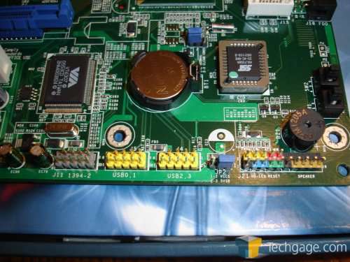
At the bottom of the board, there is an assortment of headers. These include one IEEE 1394 Firewire connection, a pair of USB 2.0 connections, headers for your on/off switch, HDD activity, reset and power LED. Directly above the USB headers, we see the CMOS battery and just above it and to the right, the clear CMOS jumper. While DFI kind of botched the placement of the power connections, they did well on the clear CMOS jumper. To the immediate right of the batter is the BIOS chip. DFI uses a Phoenix – Award BIOS for those of you keeping track at home.
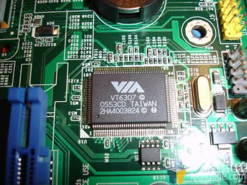
The Firewire is controlled by a dedicated VIA chip that is located directly above the Firewire headers themselves.
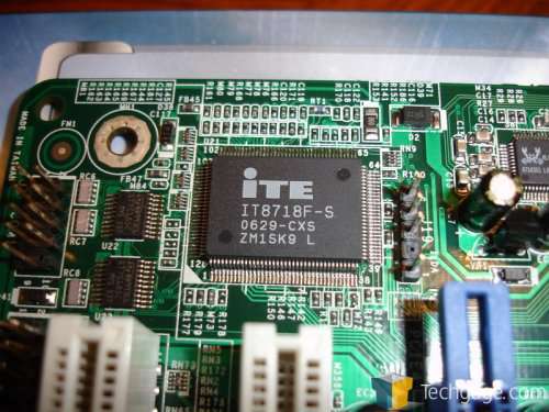
To help monitor temps, there is an ITE chip. This is where the included monitoring software, Smart Guardian, will pull its information from.
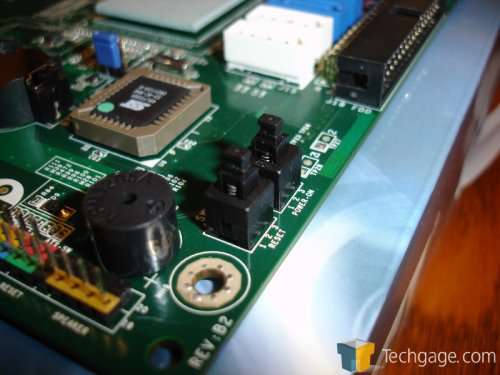
An addition to the LanParty series motherboards has made its way to the Infinity board. On the right side of the 975 X/G, near the bottom is a pair of on-board switches. The inclusion of an on/off and reset button is sure to keep the enthusiast crowd happy.
Moving up a bit, the Southbridge is located directly above the clear CMOS jumper and the BIOS chip. Directly to the right of the Southbridge are 4 SATA II ports. Capable of up to 3Gb/s, SATA II has a distinct advantage over SATA I as test have shown but rest easy, you can use SATA I hard drives without a problem. As covered earlier, RAID 1 through 5 can be run on the 975 X/G through the 4 available SATA II ports.
|
|
Support our efforts! With ad revenue at an all-time low for written websites, we're relying more than ever on reader support to help us continue putting so much effort into this type of content. You can support us by becoming a Patron, or by using our Amazon shopping affiliate links listed through our articles. Thanks for your support!


